
Scientia Silvae Sinicae ›› 2026, Vol. 62 ›› Issue (3): 201-210.doi: 10.11707/j.1001-7488.LYKX20250209
• Research papers • Previous Articles Next Articles
Chunmei Yang1,Fanwei Meng1,Tongbin Liu1,Liang Chang2,Fei Zhao3,Jie Yan1,Chengwen Sun1,Yucheng Ding1,*( )
)
Received:2025-04-08
Revised:2025-08-25
Online:2026-03-15
Published:2026-03-12
Contact:
Yucheng Ding
E-mail:dingyucheng@nefu.edu.cn
CLC Number:
Chunmei Yang,Fanwei Meng,Tongbin Liu,Liang Chang,Fei Zhao,Jie Yan,Chengwen Sun,Yucheng Ding. Blind Zone Compensation and Distortion Correction Method in Measuring Surface Morphology of Ultra-Thin High-Density Fiberboard Slab with Line Laser[J]. Scientia Silvae Sinicae, 2026, 62(3): 201-210.
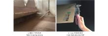
Fig.1
Ultra-thin high-density fiberboard (HDF) and slabs"
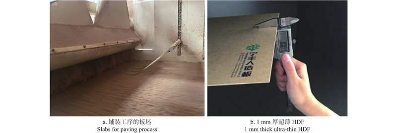

Fig.2
Macroscopic and microscopic composition of poplar micron fibers"
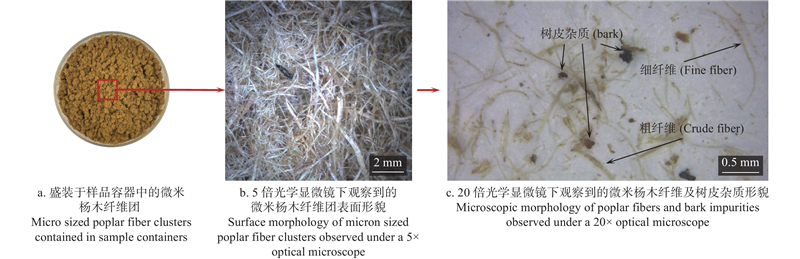
Fig.3
Line laser direct triangulation schematic diagram"

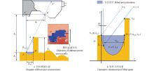
Fig.4
Geometric relations and quadratic curve estimation of blind zones for line laser blind zones"
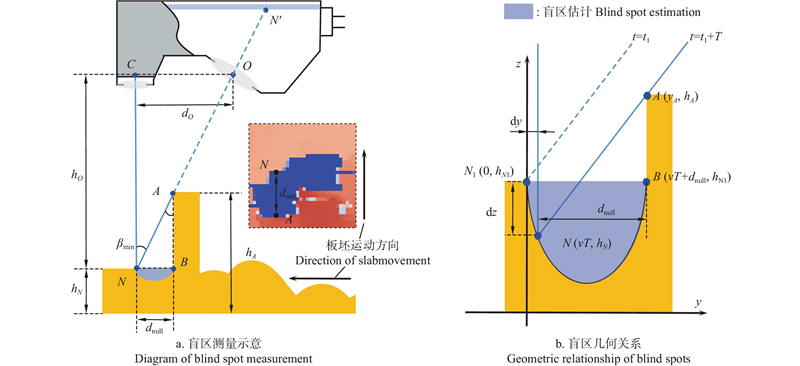
Fig.5
Line laser image distortion at different deflection angles"
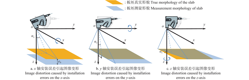
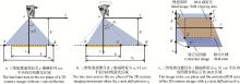
Fig.6
Aberration correction of line laser images"
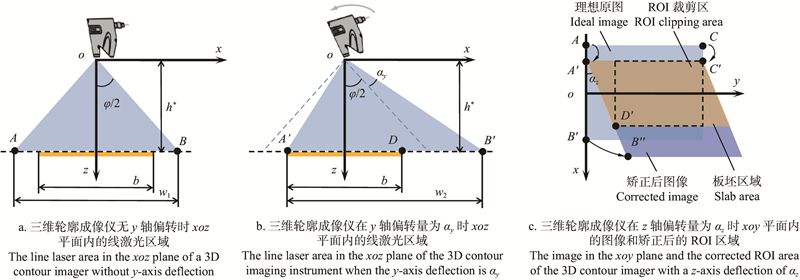
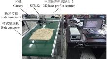
Fig.7
Test platform"


Fig.8
3D morphology of the surface layer of the slab fused by line laser"
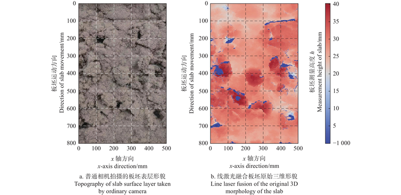
Fig.9
Blind zone compensation results of line laser images"
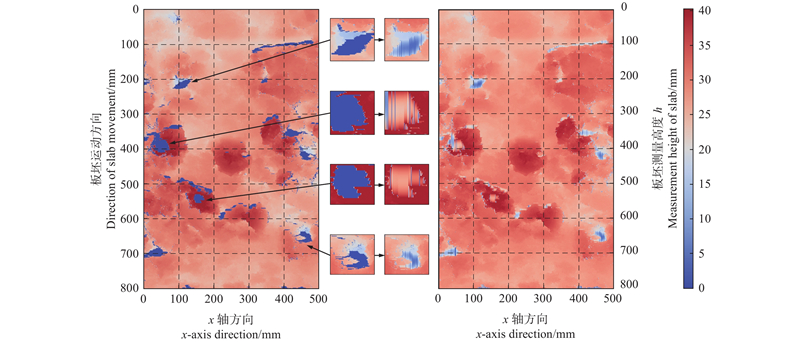
Fig.10
Height correction results of different x-axis deflection angles αx"
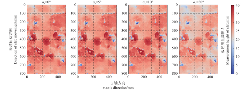
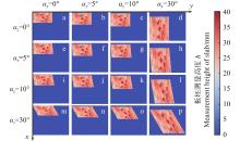
Fig.11
Line laser image correction results of different y-axis and z-axis deflection angles αy, αz (orthogonal plots)"
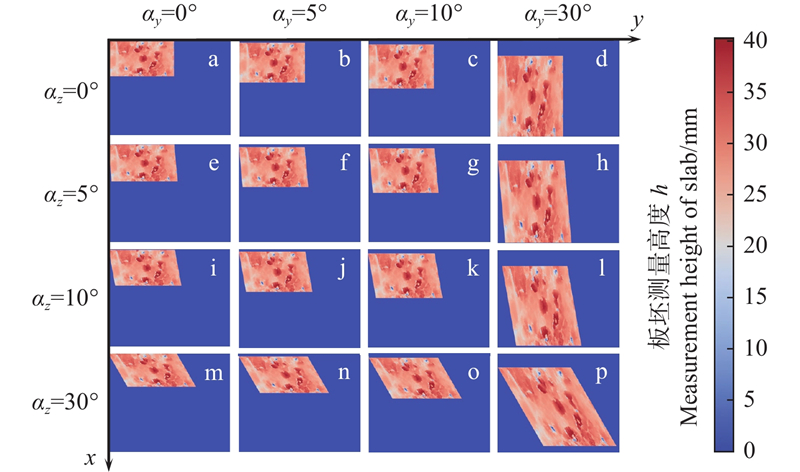
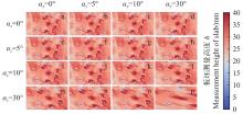
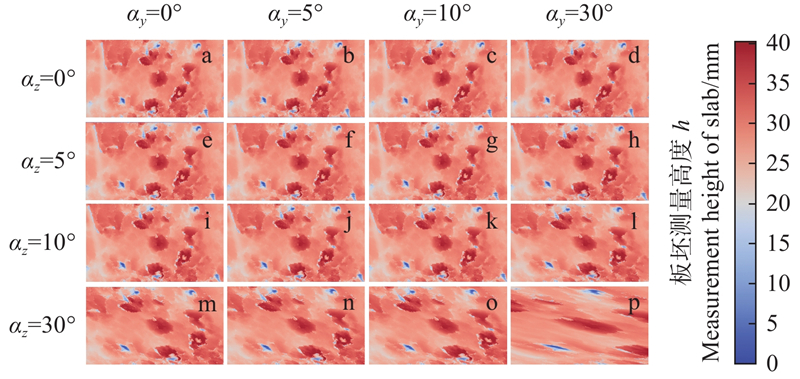
Fig.12
ROI region cropping results of different y-axis and z-axis deflection angles αy, αz"
|
陈光伟, 张峻逍, 李朝晖, 等. 中密度纤维板板坯密度与含水率对热压板间距误差的影响. 森林工程, 2025, 41 (4): 827- 833.
doi: 10.7525/j.issn.1006-8023.2025.04.016 |
|
|
Chen G W, Zhang J X, Li Z H, et al. Effect of medium density fiberboard slab density and moisture content on the spacing error of hot pressing plate. Forest Engineering, 2025, 41 (4): 827- 833.
doi: 10.7525/j.issn.1006-8023.2025.04.016 |
|
|
董 洁, 王宗平, 欧登荧, 等. 基于线激光扫描的叶片三维型面重构方法. 四川大学学报(自然科学版), 2023, 60 (3): 110- 117.
doi: 10.19907/j.0490-6756.2023.034001 |
|
|
Dong J, Wang Z P, Ou D Y, et al. Reconstruction method of blade 3D profile based on line-laser scanning. Journal of Sichuan University (Natural Science Edition), 2023, 60 (3): 110- 117.
doi: 10.19907/j.0490-6756.2023.034001 |
|
|
范承成, 德晓薇, 郭金家, 等. 基于三角位移法姿态矫正的激光线扫描海底地形三维测绘. 光学精密工程, 2022, 30 (10): 1170- 1180.
doi: 10.37188/OPE.20223010.1170 |
|
|
Fan C C, De X W, Guo J J, et al. 3D mapping of submarine topography by laser line scanning based on pose correction by triangular displacement method. Optics and Precision Engineering, 2022, 30 (10): 1170- 1180.
doi: 10.37188/OPE.20223010.1170 |
|
|
谷晴晴, 李 浩, 丁 影, 等. 非量测数码相机三种检校方法的适用性评价. 遥感信息, 2020, 35 (3): 138- 142.
doi: 10.3969/j.issn.1000-3177.2020.03.019 |
|
|
Gu Q Q, Li H, Ding Y, et al. Applicability evaluation of three calibration methods for non-metric digital cameras. Remote Sensing Information, 2020, 35 (3): 138- 142.
doi: 10.3969/j.issn.1000-3177.2020.03.019 |
|
| 李明臻. 2023. 道路巡检无人机视角下的路面图像变换与拼接方法. 西安: 长安大学. | |
| Li M Z. 2023. Road surface image transformation and stitching method under the perspective of road inspection unmanned aerial vehicle. Xi’an: Chang’an University. [in Chinese] | |
|
彭 妍, 郭君斌, 于传强, 等. 基于平面变换的高精度相机标定方法. 北京航空航天大学学报, 2022, 48 (7): 1297- 1303.
doi: 10.13700/j.bh.1001-5965.2021.0015 |
|
|
Peng Y, Guo J B, Yu C Q, et al. Calibration method for high precision camera based on plane transformation. Journal of Beijing University of Aeronautics and Astronautics, 2022, 48 (7): 1297- 1303.
doi: 10.13700/j.bh.1001-5965.2021.0015 |
|
| 邱 益, 张康宁, 梁 杰. 基于线激光位移传感器的孔毛刺高度测量系统. 仪表技术与传感器, 2022 (6): 105- 108. | |
| Qiu Y, Zhang K N, Liang J. Hole burr height measurement system based on linear laser displacement sensor. Instrument Technique and Sensor, 2022 (6): 105- 108. | |
| 邵雪婧. 2023. 覆贴超薄高密度纤维板的可饰面胶合板工艺优化研究. 泰安: 山东农业大学. | |
| Shao X J. 2023. Study on process optimization of veneering plywood covered with ultra-thin high density fiberboard. Tai’an: Shandong Agricultural University. [in Chinese] | |
|
苏 涵, 任永杰, 杨凌辉, 等. 基于激光三角法的同步扫描形貌测量传感器. 传感技术学报, 2016, 29 (12): 1791- 1796.
doi: 10.3969/j.issn.1004-1699.2016.12.002 |
|
|
Su H, Ren Y J, Yang L H, et al. Synchronously scanning sensor based on laser triangulation for measuring surface profile. Chinese Journal of Sensors and Actuators, 2016, 29 (12): 1791- 1796.
doi: 10.3969/j.issn.1004-1699.2016.12.002 |
|
|
孙有春, 庞亚军, 白振旭, 等. 激光三角测量法应用技术. 激光杂志, 2021, 42 (4): 1- 8.
doi: 10.3969/j.issn.1672-8513.2014.02.014 |
|
|
Sun Y C, Pang Y J, Bai Z X, et al. Application technology of laser triangulation. Laser Journal, 2021, 42 (4): 1- 8.
doi: 10.3969/j.issn.1672-8513.2014.02.014 |
|
| 吴博文, 冯国强. 激光三角法测距原理研究. 价值工程, 2020, 39 (22): 242- 244. | |
| Wu B W, Feng G Q. Research on principle of laser triangulation ranging. Value Engineering, 2020, 39 (22): 242- 244. | |
| 徐俊峰. 2012. 激光三角法测距系统. 长春: 长春理工大学. | |
| Xu J F. 2012. The system of laser triangulation measuring. Changchun: Changchun University of Science and Technology. [in Chinese] | |
|
徐思源, 班兆军. 基于多线激光的大尺寸水冷板高度测量系统. 仪表技术与传感器, 2024 (3): 57- 61, 95.
doi: 10.3969/j.issn.1002-1841.2024.03.010 |
|
|
Xu S Y, Ban Z J. Large-size water-cooled plate height measurement system based on multi-line laser. Instrument Technique and Sensor, 2024 (3): 57- 61, 95.
doi: 10.3969/j.issn.1002-1841.2024.03.010 |
|
| 徐兆军, 倪申健, 马辉贤. 基于斜射式激光三角测量锯材宽度的研究. 光学技术, 2018, 44 (3): 339- 343. | |
| Xu Z J, Ni S J, Ma H X. Study on the measurement of sawn timber width based on oblique laser triangulation system. Optical Technique, 2018, 44 (3): 339- 343. | |
|
俞圣池, 李佳康, 熊鑫泉, 等. 基于线激光三角测距法的鱼体测距研究. 渔业现代化, 2024, 51 (1): 80- 89.
doi: 10.3969/j.issn.1007-9580.2024.01.010 |
|
|
Yu S C, Li J K, Xiong X Q, et al. Research on fish ranging based on line laser triangulation ranging method. Fishery Modernization, 2024, 51 (1): 80- 89.
doi: 10.3969/j.issn.1007-9580.2024.01.010 |
|
|
张 未, 吕志娟, 徐兆军, 等. 基于激光三角测距的锯材表面缺陷检测方法. 林业工程学报, 2017, 2 (6): 116- 120.
doi: 10.13360/j.issn.2096-1359.2017.06.020 |
|
|
Zhang W, Lü Z J, Xu Z J, et al. Detecting method for surface defect of swan timber based on laser triangulation. Journal of Forestry Engineering, 2017, 2 (6): 116- 120.
doi: 10.13360/j.issn.2096-1359.2017.06.020 |
|
|
张文治. 浅析超薄高密度纤维板连续平压生产线关键技术和设备. 中国人造板, 2022, 29 (2): 8- 13.
doi: 10.3969/j.issn.1673-5064.2022.02.003 |
|
|
Zhang W Z. Technology and equipment for continuous press of ultra-thin high density fiberboard. China Wood-Based Panels, 2022, 29 (2): 8- 13.
doi: 10.3969/j.issn.1673-5064.2022.02.003 |
|
|
张 镭, 邹 淼, 唐启恒, 等. 热压时间和温度对酚醛树脂型超薄高密度纤维板性能的影响. 木材科学与技术, 2023, 37 (1): 68- 73.
doi: 10.12326/j.2096-9694.2022114 |
|
|
Zhang L, Zou M, Tang Q H, et al. Effects of hot-pressing time and temperature on properties of phenolic resin ultra-thin high density fiberboards. Chinese Journal of Wood Science and Technology, 2023, 37 (1): 68- 73.
doi: 10.12326/j.2096-9694.2022114 |
|
|
赵永辉, 刘雪妍, 吕 勇, 等. 基于激光点云数据的单木骨架三维重构. 森林工程, 2024, 40 (1): 128- 134.
doi: 10.3969/j.issn.1006-8023.2024.01.015 |
|
|
Zhao Y H, Liu X Y, Lyu Y, et al. 3D reconstruction of single wood skeleton based on laser point cloud data. Forest Engineering, 2024, 40 (1): 128- 134.
doi: 10.3969/j.issn.1006-8023.2024.01.015 |
|
|
Badin N, Campean M, Lengyel K, et al. Property improvement of thin high-density fiberboard panels used as door-skins. BioResources, 2018, 13 (1): 1042- 1054.
doi: 10.15376/biores.13.1.1042-1054 |
|
|
Gruber L, Seidl L, Zanetti M, et al. Calorific value and ash content of extracted birch bark. Forests, 2021, 12 (11): 1480.
doi: 10.3390/f12111480 |
|
|
Kim J I, Kim H C, Kim T. Robust mosaicking of lightweight UAV images using hybrid image transformation modeling. Remote Sensing, 2020, 12 (6): 1002.
doi: 10.3390/rs12061002 |
|
|
Luo P, Yang C M, Wang T. Making ultra-thin high density fiberboard using old corrugated container with kraft lignin. BioResources, 2022, 17 (2): 2696- 2704.
doi: 10.15376/biores.17.2.2696-2704 |
|
|
Oka T, Nakajima H, Tsugai M, et al. Development of a micro-optical distance sensor. Sensors and Actuators A: Physical, 2003, 102 (3): 261- 267.
doi: 10.1016/S0924-4247(02)00395-3 |
|
| Pierce D S, Ng T S, Morrison B R. 1992. A novel laser triangulation technique for high precision distance measurement. Conference Record of the 1992 IEEE Industry Applications Society Annual Meeting, Houston, TX, USA, IEEE, 1762−1769. | |
|
Sansoni G, Trebeschi M, Docchio F. State-of-the-art and applications of 3D imaging sensors in industry, cultural heritage, medicine, and criminal investigation. Sensors, 2009, 9 (1): 568- 601.
doi: 10.3390/s90100568 |
|
| Sun Q, Yi B, Yan X, et al. Multi-functional infrared moisture meter rapid determination of moisture content of granules. Lishizhen Medicine and Materia Medica Research, 2016, 27, 2408- 2409. | |
|
Zhang S. High-speed 3D shape measurement with structured light methods: a review. Optics and Lasers in Engineering, 2018, 106, 119- 131.
doi: 10.1016/j.optlaseng.2018.02.017 |
|
|
Zuo Q, Salleh K M, Wang C H, et al. Prediction and analysis of properties of ramie fiber staple yarn reinforced unsaturated polyester composite based on fiber packing density. Composites Part B: Engineering, 2022, 237, 109869.
doi: 10.1016/j.compositesb.2022.109869 |
| [1] | Qingjue Han,Jiangling Xiao,Xi Yan,Zhanxiong Hu,Jijing Sun. Adhesion Performance of Bionic Goat Hoof Track Shoes in Soft Geological Conditions of Forested Areas [J]. Scientia Silvae Sinicae, 2025, 61(10): 190-200. |
| [2] | Fang Gu,Mingyang Song,Yang Fan,Tenghui Feng,Lin Zhu,Mingqiang Zhu. Design and Performance Test of a Roller-Type Machine for Leaf Stripping and Peeling of Eucommia ulmoides in Leaf-Used Forests [J]. Scientia Silvae Sinicae, 2025, 61(10): 201-210. |
| [3] | Hu Wanming;Jin Ritian;Qi Yingjie;Xu Yang. Transmission Path of High Handle Power Chain Saw Machine Vibration Produced in China [J]. Scientia Silvae Sinicae, 2011, 47(1): 118-123. |
| Viewed | ||||||
|
Full text |
|
|||||
|
Abstract |
|
|||||